Figure 2. | Cone-beam computed tomography measurements. |
.jpg "View Figure")
.jpg)
.jpg "View Figure")
.jpg "View Figure")
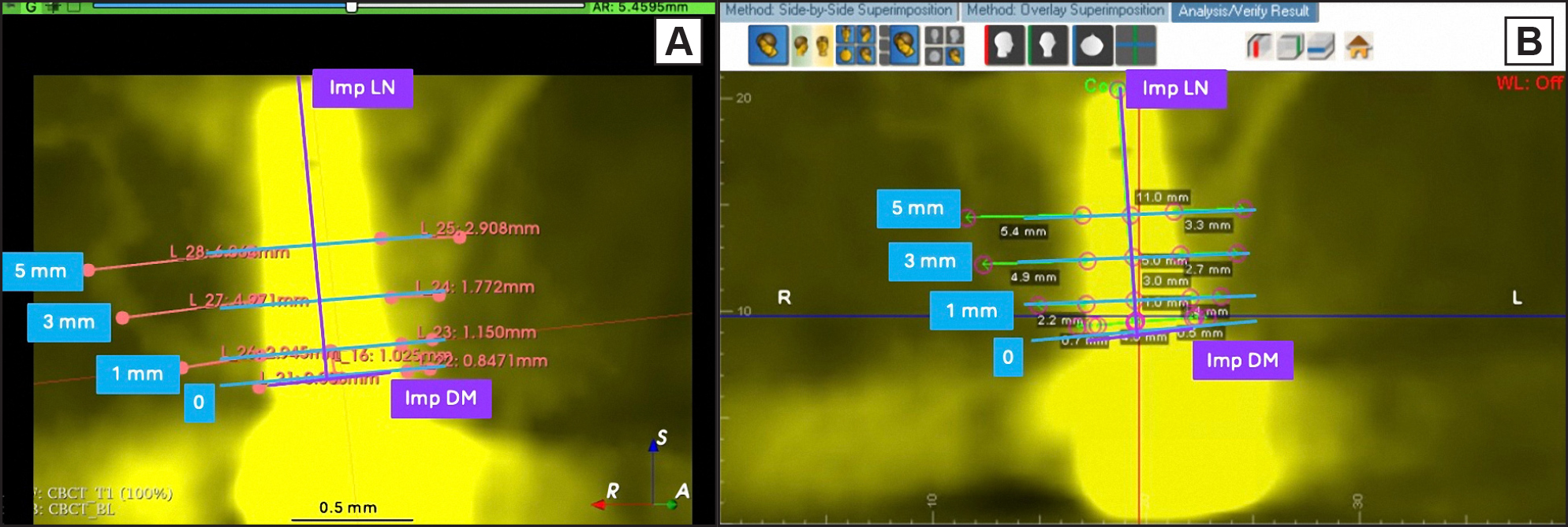
Measurements were illustrated for time point T1 for case 5 (Implant #14) on 3D Slicer (panel A), and Dolphin Imaging (panel B). Blue lines mark the landmarks at the implant shoulder (0), at 1 (1 mm), 3 (3 mm), and 5 mm (5 mm) apical to the implant shoulder for measurement of bone thickness at both buccal and palatal of implant #14 in a cross-sectional view at the mid-sagittal implant slice plane. Additionally, measurements in purple were annotated for implant diameter (Imp DM), and implant length (Imp LN). |