Figure 3. | 3D Slicer superimposition workflow. |
.jpg "View Figure")
.jpg "View Figure")
.jpg)
.jpg "View Figure")
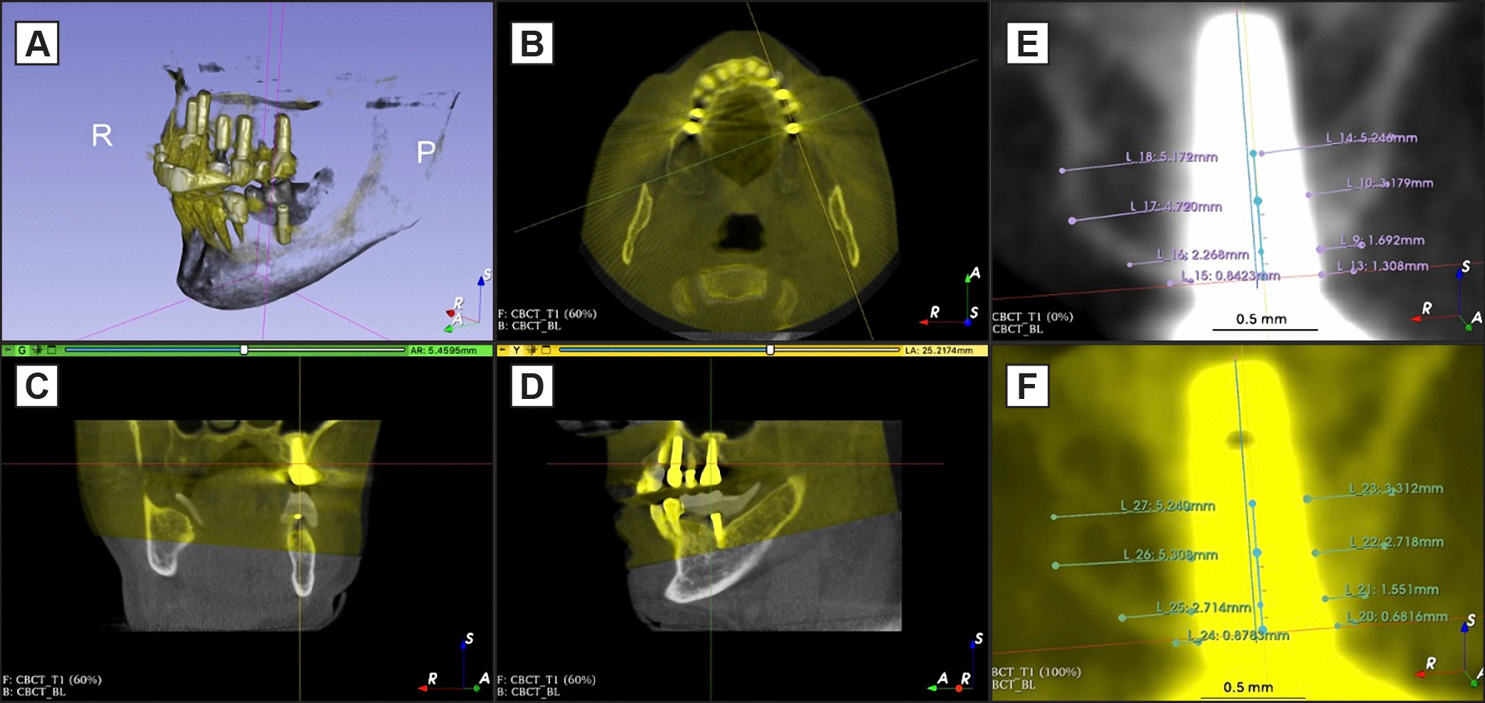
The initial superimposition of the two volumes, BL (white) and T1 (yellow), was achieved through manual approximation (plane A). Finer alignment was followed by adjustments in the 2D axial (plane B), sagittal (plane C), and coronal (plane D) views until an acceptable match was reached. Sagittal views of the implant were used in identical cut-planes for measurements in BL (plane E) and T1 (plane F). |