Figure 4. | Dolphin Imaging superimposition workflow. |
.jpg "View Figure")
.jpg "View Figure")
.jpg "View Figure")
.jpg)
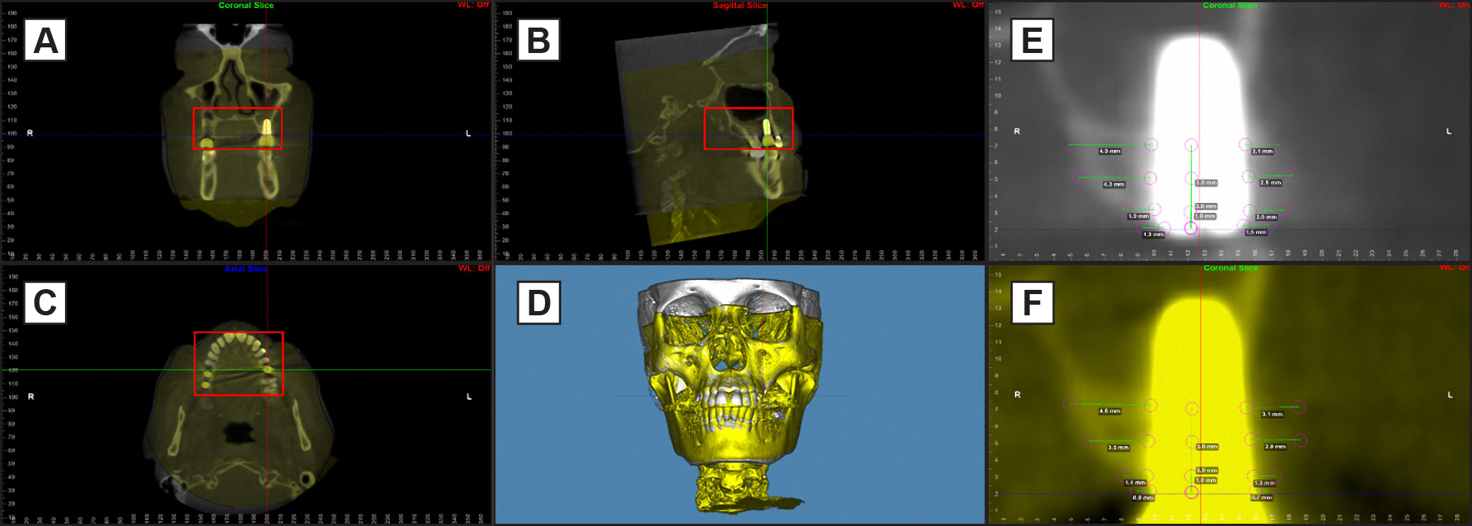
BL was used as the first volume, displayed in white, with T1 added as the second volume, displayed in yellow (planes A, B, C). The superimposition was performed using Voxel-based superimposition feature with a red cube set in the area of interest (maxilla in planes A, B, C). Finer alignment was achieved by marking a sub-region for auto-superimposition (plane D). Annotations were made using the digitize/measurement feature. The distance between landmarks was automatically calculated and displayed as vertical and horizontal 2D lines for BL (plane E) and T1 (plane f). |